PDM Production Analizer Catalogue ( 685KB )

Best partner for productivity improvement!
Production analizer which indicates and analizes the process status of the machines.
Data control can be done up to 30 sets per one PC.


ŠÈ’Pà–¾
2008/11/08 Summary 2008/11/22 Connection method
2008/11/22 Operation 2009/05/02 PDM Application

ŠÈ’Pà–¾
ŠÈ’Pà–¾
PDM has been developed, for improvement of productivity efficiency.
The indicator guarantees a certain level of the vibration-proof and displays the real time production status.
Befor operation, set the scheduled numbers on the first line, and the current numbers are shown on the second line, and the process status (% or + or -) is displayed on the third line.
Relay output such as "stop" or "schedule finish" is available from input signals such as operation, stop, emergency stop, and preparation stop.
It can output the work results in an Excel file or graph display with PC.
ŠÈ’Pà–¾
One of the constitution example is shown in chart below. PDM itself can work, however for getting the records of the operation status, connection with PC is necessary.


ŠÈ’Pà–¾
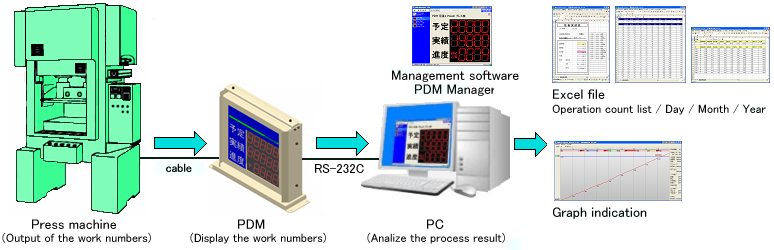
Count function is available as a basic one and a counter input terminal is prepared. When counter inputs "ON", it starts to count.

PDM Production Analizer movie 1 ( count up )

ŠÈ’Pà–¾
Please connect correctly according to the following diagram and description.

ŠÈ’Pà–¾

Name Description
Set machine port Connector Connector between setting device (PDM-T) & PDM
PDM-T
IN1 Counter Input When input eONf, production number is added one by one.
IN2 Operation / Stop Input ON : Operation OFF: Stop
IN3 Emergency stop Input When emergency stop, input fONf
IN4 Preparation time Input During preparation time, input eONf
Out1 Stop Output During eStopf eEmergency Stopf ,or ePreparation timef it outputs.
Out2 Schedule completion Output When it comes to the scheduled numbers by parameter setting, output eONf
RS-485+(1)
RS-485-(1)
RS-485 Communication(1) Communication with PC.
RS-485+(2)
RS-485-(2)
 RS-485 Communication(2) Communication with PC & plural numbers of PDM.
RS-485E RS-485 Communication(E) When terminate, the last PDM should be short-circuited between RS-485-(2) & RS-485E
AC100V`AC220V Power Supply AC100V or AC220V
F.G. Ground terminal Be sure to ground.

ŠÈ’Pà–¾
When connect with PC, use the converter eModel:SI-35f between RS-232CÌRC485.
When no RS-232C port in PC, the converter eModel: SRC06-USBf is necessary, between RS-232C Ì USB converter.


ŠÈ’Pà–¾
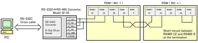
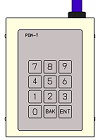
Before operation, set the "scheduled numbers" and reset the "result numbers" at 0, and choose the "progress status" from 9 classes. ( Refer to the following description "Menu 1", No. 4 )
The scheduled numbers shows scheduled production numbers, and the result numbers shows current production numbers. During opration, reset of the result numbers is capable.

PDM Production Analizer movie 2 ( How to change the scheduled no. & result no. & progress status )


When depress the eENTf key of PDM-T for a few seconds, it moves to eMENU MODE 1f from the basic screen.
Progress column repeats blinking, and is prepared for the menu number input.
Parameter setting from eMENUf is as following.
ŠÈ’Pà–¾
No. Parameter set Description
1 Scheduled numbers Scheduled numbers of production.
2 Target numbers Current production numbers. The number is automatically counted up by tact time setting.
3 Result numbers Everytime IN1 (count Input) becomes eONf, the result number is counted up.
4 Progress column indication sorts Input the class which is indicated on the progress column.
0 - progress degree }
The difference between
the scheduled numbers and the result numbers.
1 - progress degree %
The ratio of the result numbers to the scheduled numbers
.
2 - target numbers  
Production numbers which should be produced just on that time.

3 - numbers of remainder 
The difference between the result numbers and the target numbers
.
4 - target ratio 
The ratio of the result numbers to the target numbers
.
5 - machine stop status.
6 - latest tact time.
7 - average tact time.
8 - estimated completion time.
5 Pre-scaler 0 - Multiple pre-scaler
IN : Getting ON signal every one time, it performs eNf times count up by pre-setting.
ex) When e4f is set by multiple pre-scaler, e4fis added by one input signal.
1 - Division pre-scaler
IN: Getting ON signal eNf times, it performs eOnef time count up by pre-setting.
ex) When e4 is set by division pre-scaler, eOnef is added by 4 input signalsf.
6 Completion output setting Itfs usually set at e0f, and when production numbers exceed the scheduled numbers, OUT2 ( scheduled completion output )  turns eONf.
When e -100f is prepared as completion output numbers and then production numbers comes to e-100f,Out 2 ( scheduled completion output ) turns eONf
ex) Scheduled numbers:2000, completion output setting: -100.
When the production numbers comes to 1900, OUT2 turns eONf
7 Stop time Stop time during operation. Operation time, process stop time, emergency stop time and preparation stop time can be cleared by PDM-T.
8 Tact time setting Standard time to produce one product.

When depress the eBAKf key of PDM-T for a few seconds, it moves to eMENU MODE 2f form the basic screen.
ŠÈ’Pà–¾
No. Parameter set Description
1 Daily record execution set Set the day record.
2 Present time adjustment When starting operation, set the present time by the built-in clock. Itfs capable to adjust the correct time.
3 Operation time set Set the working hours on the day. Registration up to 16 parameters are capable.
Starting time of the first parameter is regarded as eBeginning of the dayf and before that time, it is counted as the previous day operation.
2009/05/07 update.

ŠÈ’Pà–¾
ŠÈ’Pà–¾
Exclusive application, "PDM Manager" is available for PDM.
PDM Manager can be used to confirm the current production numbers and status from the office away from the factory. It can also change the scheduled numbers by remote control from the office. Status of a day production numbers can be recorded on Excel file.
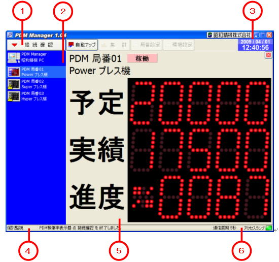
ŠÈ’Pà–¾

No. Name Description
1 Button Confirmation of connection, daily record, total count nubmers, confirmation of PDM No. ( No.1 - No.30 ) environmental setting.
2 Monitor panel Display the PDM connection status.
3 Clock Time setting should be done on the control panel of PC byeWindowsf which is shown on PDM. Daily record time of the log data depends on that of PDM.
4 Status bar Display the current production status and execution result.
5 Panel display Display an individual monitor screen or all monitor screen.
6 Cycle and access lamp Display the current communication cycle and status, which is shown by the color.

¦ PDM Manager can control plurel PDM's, up to 30 sets.
ŠÈ’Pà–¾
PDM Progress Viewer can display eDaily line graphf according to the log file recorded by PDM manager.
The graph is easy and simple to find how the production conditions were during operation. So itfs very convenient in the follow-up survey of factors lowering the production efficiency.
There are 2 kinds of graphs, one is a graph in numerical value chart (scheduled numbers
E result numbersE target numbers) and time chart( operation timeE stop time process stop timeE emergency stop timeEpreparation stop time) and itfs capable to display both charts together.
Alternative choice is capable  "display" or "non display" by the left side button, and only necessary graph chart can be displayed.

ŠÈ’Pà–¾

No. Name Description
1 Graph chart button Schedule / Result / Target Operation, Stop / Process stop / Emergency stop / Preparation stop graph is chosen individually, and display / non display alternatively.
2 Time Display the time transition.
3 Status bar Display the PDM status transition.
4 Graph Display the transition of the X axis and Y axis seguertially. X axis shows numerical value, Y shows time chart.
5 Mouse line
(Green line)
Follows the mouse cursor automatically. The current position status of this line is reflected in the status bar.
6 Status bar Display the log data from the mouse line position.

¦ PDM Progress Viewer can be printed out.

PDM Production Analizer movie 3 ( With application )